
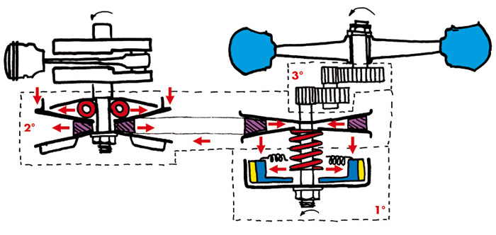
1st group – centrifugal clutch: the clutch shoes (2 or 3 according to the motor model ) expand as the motor increases revolutions under the centrifugal force and engage the clutch bell transmitting the movement to the wheel, it is possible to modify the original clutch function substituting the springs which control the shoes movement with stiffer ones, so increasing the revolutions which the clutch engages at; to be clearer it would be as if on a normal motorcycle we would release the clutch lever at higher revolutions to obtain a quicker start.
2nd group – variator: the speed variator is similar to a normal gear change with the advantage it presents no gaps while changing from one speed to another as it gives a continuous variation to the gear ratio.
It is possible to modify it mounting the Polini Transmission Kit instead of the whole group mounted on the crankshaft; it is also possible to modify the driven pulley by changing the contrast spring of the mobile semi-pulley with others with different “ strength”, to balance at the best the front variator movement, under the action of the centrifugal force which operates on the rollers.
3rd group – gears: these gears reduce the revolutions between the driven pulley and the wheel.
Their function is comparable to the one of the SPROCKET-CHAIN group in an original motorcycle.
Change them when, using a cylinder kit which increases the displacement, when you want to transform the increased power into a max. speed increase of the motorcycle; we suggest you to change these gears when you want to tune your engine as they reduce the possibility of the motor over revving.
After having seen how the transmission group is composed we can describe you its functioning; please pay attention to the diagrams:
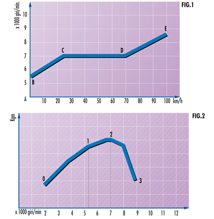
The diagram in fig. 1 shows the speed variation with the engine revolutions, fig. 2 represents the torque curve diagram. Its functioning can be theoretically divided in four well defined phases: 1° section A-B of fig. 1, speed=0 (standing motorcycle). You can accelerate as long as the clutch engages (in the ex. At 5300 rpm) without the motorcycle moving; the speed variator is in the starting position (short gear).
Diagram of fig. 2, curve section 01. This position can be compared with the neutral gear position on an original motorcycle. 2° section (B-C) of fig. 1, in point B (5300 revolutions), the clutch engages progressively “skidding” till it reaches point C (7000 revolutions). At this speed the clutch is completely engaged; the speed variator is in position of “short gear”.
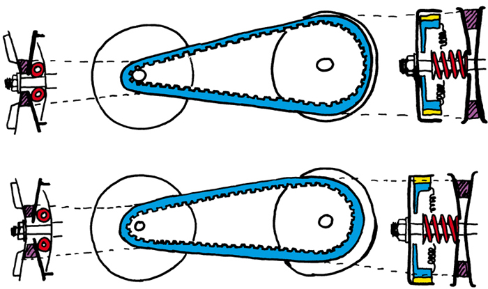
Diagram of fig. 2, 1-2 curve section : it is very important to have an high torque at disposal. Diagram of fig. 1, 3° section (C-D). The clutch is completely engaged and the engine is at its max torque rate (often it corresponds to the max. power rate); the speed variator starts changing the ratio from the “shortest gear” to the “longer gear”. As you can clearly see from the diagram of fig. 1 the speed increases while the motor revolutions remains constant.
Diagram of. fig. 2, point 2 corresponding to the max. torque rate. 4° section, D-2 fig. 1: the speed variator has reached the “longer running” position and maintains it. The engine rpm start increasing up to the max. speed.
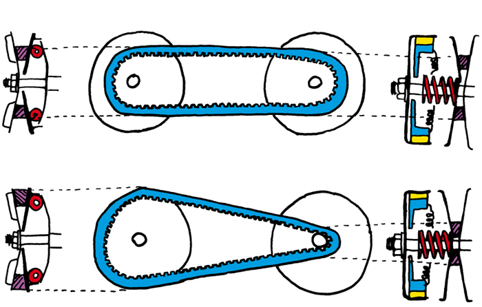
Fig. 2 diagram, curve section2-3: This is that phase usually defined “of extension”. We can now leave the theoretical part to pass to some practical advices; one of the first adjustments is the silencer changing.
Often the increased power obtained with this adjustment gives also a revolutions rate increment of the max. power. Now that we well know the transmission group functioning we can also understand that the adjustment of the speed variator, which at the beginning was perfectly regulated with the original silencer, cannot agree with the output curve obtained with the new silencer; this difference can be seen superimposing the torque curve of the original silencer with the one obtained with the new exhaust. Here you can clearly see that the revolutions at which the variation rate begins (7000 rpm) are far from the new torque curve of about 1.000 rpm.
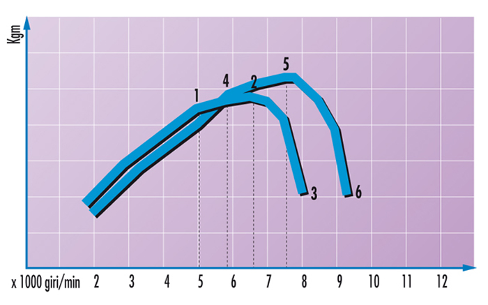
In this case you will have to lighten the speed variator rollers to move its intervention rate up to about 8.000 rpm (new max. torque rate).In point 1 (clutch engages) you can see that with the new silencer you have less power: we suggest you to mount stiffer clutch springs in order to move its engagement rate from 5.300 up to 6.200 rpm. This adjustment will allow you quicker starting.
As explained in the previous example it is possible that after an engine modification you note results which could seem opposed: that ‘s why references and the following recording of the preformance, noticeable on road, have great importance.